Industry News
Curation by industry experts
Hot Articles
Popular Tags
How to check voltage drop when buying 12V neon rope lights wholesale
Uneven brightness and color shifts can turn a lighting order into a costly procurement problem. When sourcing 12V neon rope lights wholesale, check voltage drop across the intended run length, not just the price per meter or the rated brightness. A low unit price can be offset by extra power feeds, larger cables, additional installation labor, or replacement stock.
The decisive figure is the voltage available at the far end of the light under operating load. A supplier’s maximum run-length claim is useful only when its test conditions match the intended product, power feed, cable length, and acceptable brightness variation.
Why a 12V rating does not guarantee an even run
Most 12V LED neon rope lights use a constant-voltage power supply and have conductive paths running through the product. Those paths have resistance. As current flows, voltage is lost along them, leaving less voltage for LEDs farther from the feed point. The result can be a dimmer far end or, with some products, a visible color difference.
The extent of the problem depends on more than length. Wattage per meter, the resistance of the internal conductors, the electrical design, feed-wire resistance, connectors, and operating temperature all matter. Two products rated at 12V and 10 W/m may therefore perform differently over the same distance.
Color-changing products need particular care. An RGB or RGBW rope may have different current paths for different channels, and the visual effect can change with the selected color and dimming level. A white setting made by combining channels can reveal a color shift that is not obvious when testing a single channel.
Voltage drop in the light itself must also be separated from voltage drop in the cable between the power supply and the light. A rope may perform acceptably when connected directly to a bench supply but fail when installed at the end of a long, undersized lead.
Get a comparable run-length claim before requesting prices
Ask each supplier to state the maximum continuous run for the exact item being quoted, including its color or channel configuration, rated wattage, and feed arrangement. “Maximum 5 meters” is incomplete unless it is clear whether the rope is powered from one end, both ends, or through intermediate feeds.
A useful technical submission should include:
- Rated voltage and operating voltage range, if specified by the manufacturer.
- Rated watts per meter and tolerance, with the measurement conditions.
- Maximum recommended run length for each proposed feed configuration.
- Cutting intervals and the permitted methods for joining or injecting power.
- Recommended supply voltage and any minimum voltage required for acceptable operation.
- Test results showing voltage and brightness at the supply end and far end of the stated run.
The brightness criterion matters as much as the voltage reading. A supplier may regard a run as functional because all LEDs remain lit, while the installation requires a consistent appearance across an illuminated outline. Agree on what constitutes acceptable end-to-end variation rather than relying on terms such as “no visible drop.”
For a commercial display where adjacent runs are viewed together, ask whether the supplier can provide measurements in lux or luminance under a defined setup. Lux readings depend on sensor position, distance, and surroundings, so values are only comparable when the same setup is used. Where appearance is critical, combine instrument readings with a visual review under representative viewing conditions.
Measure voltage under load, not on an unplugged sample
Request a sample of the actual run length to be purchased, or a representative assembly using the same product, connectors, and construction. A short sample can confirm color and finish, but it cannot establish how a longer run performs. Keep the sample’s product code and specification linked to the quotation so that the test applies to the item ultimately ordered.
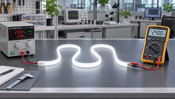
Use a regulated constant-voltage 12V DC supply with adequate current capacity, a suitable multimeter, and the intended connection arrangement. Set up the rope as it will be used, with the same feed direction and, where practicable, the same lead length and connectors. Observe the manufacturer’s instructions for powering the sample: some products should not be operated for extended periods while tightly coiled because heat can build up.
- Switch the product on at the intended setting. For a single-color rope, test at full output. For RGB or RGBW, test relevant colors and the intended white setting; record each mode because channel loading differs.
- Measure at the rope’s input terminals. Record the DC voltage where the feed actually enters the product, rather than relying only on the power supply’s display or open-circuit output.
- Measure at the far end. Use accessible test points provided by the manufacturer, or have the supplier expose suitable points on a test sample. Measure across the corresponding positive and return conductors while the rope remains energized.
- Record current and operating conditions. Note run length, product configuration, cable size and length, supply voltage, mode, and whether the product has reached a stable operating temperature.
- Compare appearance and readings. Document the input-to-end voltage difference alongside brightness or visual observations. Repeat the setup for competing samples.
If the rope’s far-end conductors are sealed and cannot be reached without damage, ask for a purpose-prepared test sample or witnessed supplier measurements. Do not pierce the jacket of stock intended for installation: damage can compromise insulation or the claimed ingress protection. Electrical testing and any modification should be carried out by a competent person using the manufacturer’s instructions.
As an illustrative calculation, if a loaded rope receives 12.0V at its input and measures 10.8V at the far end, the measured drop within that run is 1.2V, or 10% of the input voltage. This is an example, not a universal pass or fail limit. Whether it is acceptable depends on the product’s operating range and the agreed appearance criterion.
Also measure at the power supply output. If it reads 12.0V but the rope input reads 11.4V, the feed cable and connections account for a 0.6V reduction before the current enters the rope. The rope’s internal drop must then be assessed from its input, not from the supply output alone.
Use calculations to screen offers, then test the assembly
A basic power calculation helps size the supply and identify cables that deserve closer scrutiny. For example, an 8 m run rated at 9 W/m has a nominal load of 72 W. At 12V, that corresponds to approximately 6 A using current = power ÷ voltage. Actual current can differ from the nominal estimate, so use measured current and the manufacturer’s requirements for final component selection.
For a simple two-wire feed, the cable’s approximate voltage drop is current multiplied by the total resistance of both the outgoing and return conductors. That distinction matters: a 5 m route from the supply to the rope has approximately 10 m of conductor in the electrical loop. Longer cables, smaller conductor cross-sections, higher currents, and poor connections increase losses.
Do not apply that same simple calculation to the entire illuminated rope as though all its current flowed to the far end. LEDs draw current along its length, so current in the internal conductors changes from one point to another. A reliable estimate needs the actual conductor resistance and circuit arrangement; a loaded end-to-end test captures the combined effect more directly.
Allow an appropriate margin when selecting a power supply rather than matching its rating exactly to nominal LED wattage. The required margin depends on the supply manufacturer’s instructions, operating environment, loading conditions, and applicable installation requirements. Confirm that any dimmer or controller is also rated for the actual voltage, current, and channel arrangement.
Compare feed arrangements as installed systems
A single-end feed is simple, but the internal conductors carry the greatest combined current near the input. If the far end is too dim, splitting the lighting into shorter independently fed sections can reduce the distance over which voltage is lost. Feeding both ends or adding intermediate injection points can also help, provided the product and connection method are designed for that arrangement.
Those alternatives are not interchangeable without engineering checks. Confirm the permitted wiring diagram, polarity, connector ratings, and protection requirements with the supplier. Do not join outputs of separate power supplies together unless their manufacturers explicitly permit the configuration and it has been properly designed. A second feed also needs an adequately sized cable; a long, thin injection lead can simply move the voltage-drop problem elsewhere.
For cost comparison, put each offer on the same installed basis. Include the number of power supplies and controllers, feed and extension cable, connectors, mounting accessories, labor, and any additional protected connection points. A higher-priced rope with a verified longer single-feed run may cost less overall than a cheaper product that requires several extra feeds. The reverse can also be true if the layout already has accessible power points.
Compare products against the actual layout rather than only a full-reel price. An order containing many short independent signs has different requirements from a continuous architectural outline. Cutting intervals, usable lengths, connector placement, and offcut waste can materially change the cost per completed installation.
Turn the sample result into an order requirement
A successful sample is useful only if the bulk product retains the relevant construction and performance. Attach the agreed specification to the purchase order: product code, color or channel configuration, wattage, cut interval, maximum run and feed method, and the test conditions used to accept the sample.
Define the acceptance method in measurable terms where possible. For example, specify the test length, supply voltage measured at the rope input, operating mode, cable arrangement, warm-up condition, and the acceptable far-end voltage or brightness variation. If visual consistency is the governing requirement, retain an approved reference sample and agree on viewing conditions as well as any instrument-based limits.
Ask how the supplier controls changes to LED components, internal conductor construction, and rated wattage. A change that preserves the external appearance or nominal 12V label can still alter current draw or voltage-drop performance. The order should require notification and approval of relevant changes, along with an agreed remedy if delivered material fails the acceptance test.
Before approving volume production, repeat the agreed check on a production sample or agree on an appropriate inspection plan. The commercial decision then rests on evidence from the intended run length and wiring arrangement—not on a reel label or a short demonstration piece.
Recommended News
 Eco PackagingVietnam Briefing Checklist Highlights EU Packaging Rules for BuyersEU packaging rules affect buyers sourcing from Vietnam. Explore the Vietnam Briefing checklist and key PPWR questions to verify before placing an order.Packaging Supply ExpertNov 17, 2026
 Commercial LEDHow to check voltage drop when buying 12V neon rope lights wholesaleBuying neon rope lights wholesale 12v? Learn how to test voltage drop, compare supplier claims, and avoid costly brightness issues before placing an order.Commercial Tech EditorNov 17, 2026
 Policy & RegulationsEU Proposal to Restrict Chinese Furniture Imports Draws Strong Industry OppositionEU proposal to restrict Chinese furniture imports faces industry opposition. Explore potential supply chain and cost impacts, and what buyers should watch.Nov 16, 2026
 Supply Chain InsightsHow to improve supply chain resilience through supplier diversificationStrengthen supply chain resilience with a practical guide to supplier diversification, from mapping hidden risks to qualifying alternatives and testing switch plans.Nov 16, 2026