Industry News
Curation by industry experts
Hot Articles
Popular Tags
How to check device compatibility in KNX smart lighting systems
In KNX smart lighting systems, device compatibility depends on more than a shared KNX logo. A switch, sensor, actuator and gateway can all communicate on a KNX installation yet still fail to deliver the required lighting behavior. Before buying, check the complete control path: the communication medium, the ETS application, the available group objects, the electrical interface to the luminaires and the functions exposed through any gateway.
Start with a specific use case, such as “a presence sensor switches on a group of lights, maintains a target light level and reports the current state to the building management system.” Then trace every part of that behavior through the proposed devices. This makes gaps visible before they become commissioning changes or replacement orders.
Check the exact product and its ETS application
KNX certification is a useful starting point for identifying products designed to participate in the KNX ecosystem. It does not, by itself, establish that a particular device supports every control function required by the project. Assess the exact model and application, rather than relying on a product family description.
Obtain the manufacturer’s ETS product database entry and application documentation early. Import the product into the ETS version intended for the project and review its parameters and communication objects. Check that the planned hardware variant is supported and that the required functions are available in the application configuration.
This matters because a product may be described broadly as a dimming actuator while its selectable behavior, feedback options or number of usable channels differ from the project specification. A device may also support a function only after a parameter enables the relevant object. A datasheet can establish the general capability; the ETS application shows how that capability is configured and connected.
For an existing installation, the project file is just as important as the product file. Establish which ETS version is available, whether the existing project can be opened and edited, and whether any device-specific commissioning software or manufacturer plug-in is needed. Confirm access to project passwords and device configuration credentials before committing to a modification.
Map each required function to communication objects
KNX devices exchange information through communication objects linked by group addresses. To check interoperability, compare what the sending device transmits with what the receiving device expects. Two objects with similar names are not necessarily interchangeable: their data types, meaning and configured behavior must align.
For a dimmable lighting group, the review may include separate objects for switching, relative dimming, an absolute brightness value and status feedback. A wall control might support on/off and relative dimming, while a visualisation interface expects to set an absolute level and display feedback. If the actuator lacks the necessary objects, the lights may respond to the wall control but provide an incomplete user interface elsewhere.
Build a small function matrix before finalising the bill of materials:
- Command: What action is required, and which device sends it?
- Data: Does the receiving object accept the same KNX data type and interpretation?
- Feedback: Which device reports the actual state, and which interfaces need that information?
- Configuration: Are the relevant objects enabled by the proposed parameters?
- Priority: What happens when manual control, occupancy, schedules and central commands conflict?
Include behaviour after a bus voltage failure and recovery, as well as startup values and scene recall where these matter. A sensor that sends an occupancy command and an actuator that accepts it can still produce an unsuitable result if their delay settings, override logic or recovery behaviour are incompatible with the intended sequence.
Match the KNX medium and network architecture
Identify how each device connects to the installation. KNX devices may use twisted pair, radio frequency or IP communication. A device using one medium cannot simply be connected as though it used another; appropriate KNX infrastructure and configuration are needed where media or network segments meet.
For a wired extension, check the existing line topology, available power supply capacity and the device’s bus power consumption. Also account for couplers, line allocation and installation constraints. For an RF device, consider the building construction, device placement and any need for suitable RF infrastructure. An acceptable connection on a sample bench does not establish reliable coverage throughout a finished building.
For IP-connected components, determine whether the device is a KNX IP interface, a router or another type of gateway, and whether its role matches the design. An interface used for access to a KNX installation is not automatically a substitute for an IP router used to connect KNX lines. Coordinate addressing, network access and any relevant multicast requirements with the team responsible for the IP network.
Where the project uses KNX security features, check which devices and communication paths support the required form of security and how keys will be commissioned, stored and handed over. A compatible physical connection does not guarantee that every planned device supports the same secure communication arrangement.
Verify the lighting interface beyond KNX
Many compatibility problems occur between a KNX actuator or gateway and the lighting equipment it controls. The right check depends on the electrical or control interface at that boundary.
Switching actuators and lighting loads
A switching actuator needs a suitable output rating for the connected load, but the nominal wattage alone is not enough. LED drivers can draw a high inrush current when switched on. Compare the actuator’s documented switching capability for the intended load with the driver characteristics and the number of drivers on each output. Also check the required supply arrangement and whether the design needs separate protective devices or contactors.
Dimmers, drivers and luminaires
For phase-cut dimming, match the dimmer’s supported load types and operating method to the LED driver or lamp. Check the supported load range, including the lower end: a small load can behave differently from a fully populated circuit. Consider minimum stable brightness, flicker, audible noise and the response when switching between off and low light.
A luminaire described as “dimmable” does not necessarily work with every dimming method. The driver documentation should identify the intended control interface. If consistent performance matters across a large installation, test the actual driver, luminaire and dimmer combination, including the smallest and largest planned circuit configurations.
KNX gateways and DALI or other lighting controls
A KNX-to-DALI gateway introduces another layer of compatibility. Confirm that the gateway supports the addressing, grouping, scenes and feedback required for the proposed DALI equipment. Determine which functions are handled inside the gateway and which are exposed as KNX communication objects.
For tunable white or colour control, check the supported control model at both ends. A gateway that can switch and dim a luminaire may not expose the colour-temperature or colour-control functions required by the interface. Also establish how failures are reported: a general group fault may be sufficient for some spaces, while maintenance teams may need visibility of individual control gear.
Test the intended control sequence, not just individual devices
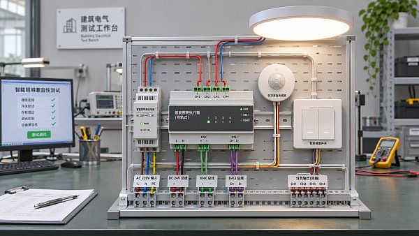
A practical compatibility test uses the proposed sensor, control device, actuator or gateway, and representative lighting load together. Configure them with the planned ETS application and exercise the functions that matter to the site. A successful on/off command is a useful starting point, but it is a poor acceptance test for a system expected to manage occupancy, daylight and manual overrides.
For example, consider a meeting room with presence detection, daylight regulation and a wall control. Test whether a user can override the automatic level, how long that override lasts, what happens when the room becomes vacant, and how the system behaves when someone returns. If daylight control is required, establish which device owns the control loop and how the light sensor is configured. Two devices independently trying to regulate the same group can create unstable or confusing behaviour.
Include transitions that are easy to miss during a demonstration: a scene recalled while the lights are off, a central off command during occupancy, a device restarting, and the restoration of bus power. Check both the physical light output and the status displayed on the wall panel or supervisory interface. A mismatch between output and feedback can make a functioning circuit appear faulty to the user.
Record the ETS application version, parameter settings, connected load and observed results. Where the final installation includes multiple driver types, test each relevant combination rather than assuming that one representative luminaire covers them all.
Assess gateways and building management integration separately
When a KNX lighting installation must exchange data with a building management system, identify the required information in both directions. The integration may need commands, actual brightness, occupancy, fault indications or energy-related data. A gateway’s support for a protocol does not mean that every KNX object will automatically appear in the external system with the required meaning.
Request a point list showing each signal, its direction, data type, units where applicable and update behaviour. Decide which system owns schedules, scenes and overrides. If both systems can issue commands, define how conflicts are resolved and what happens when the connection is unavailable.
Also review operational access. The installation may need network credentials, ETS project files, gateway configuration backups and a clear method for replacing a failed device. Compatibility at handover has limited value if the facilities team cannot maintain the configuration later.
Turn the findings into a procurement decision
Compare competing devices against the same function matrix and representative load, not just against headline descriptions. A lower-cost actuator may be adequate for simple switching, while a more capable gateway may be justified where individual fault reporting, colour control or building management integration is part of the brief. The choice depends on the required behaviour and the cost of resolving a missing function later.
Before placing the order, retain the exact model references, ETS product files, interface documentation, test results and agreed control sequence with the project records. Flag any device substitution for review against those records: a replacement with the same general purpose may have different objects, load limits or commissioning requirements. This gives procurement and commissioning teams a shared basis for deciding whether the delivered system can perform as specified.
Recommended News
 Smart LightingHow to check device compatibility in KNX smart lighting systemsSmart lighting systems KNX compatibility starts with the right checks. Discover how to verify ETS objects, gateways and lighting loads before you buy.Commercial Tech EditorNov 19, 2026
 Eco PackagingFinance Ministry Seeks Input on Government Procurement Packaging StandardsGovernment procurement packaging standards are open for consultation. Explore potential impacts for suppliers and key questions to review before commenting.Packaging Supply ExpertNov 18, 2026
 Garment MfgHow do minimum order quantities affect custom school uniform costs?Custom school uniforms wholesale costs depend on minimum order quantities. Learn how to compare price breaks, manage inventory risk, and negotiate better terms.Textile Industry AnalystNov 18, 2026
 Eco PackagingVietnam Briefing Checklist Highlights EU Packaging Rules for BuyersEU packaging rules affect buyers sourcing from Vietnam. Explore the Vietnam Briefing checklist and key PPWR questions to verify before placing an order.Packaging Supply ExpertNov 17, 2026